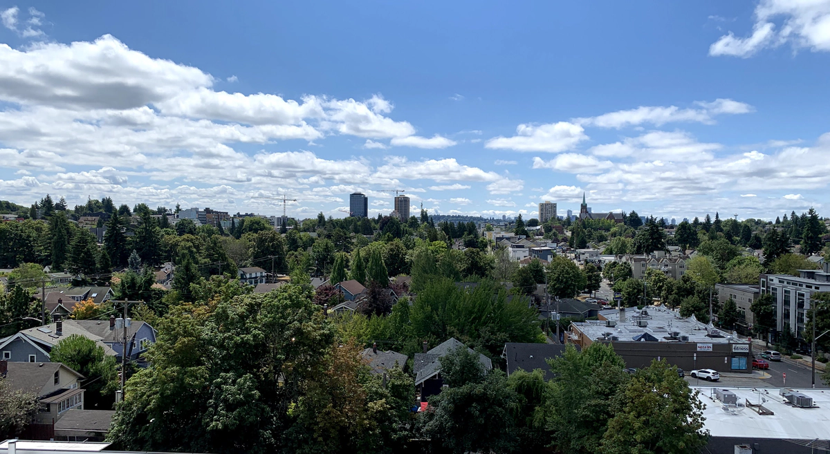
It’s shaping up to be another intense season for wildfires on the West Coast. Last year, we had about 2 weeks where the air quality was bad enough that we needed to limit our time outdoors. It’s been on my mind to stock up with supplies for wildfire season. Air filters (for reducing the amount of smoke indoors) are now plentiful, but inexpensive air quality meters are still difficult to find.
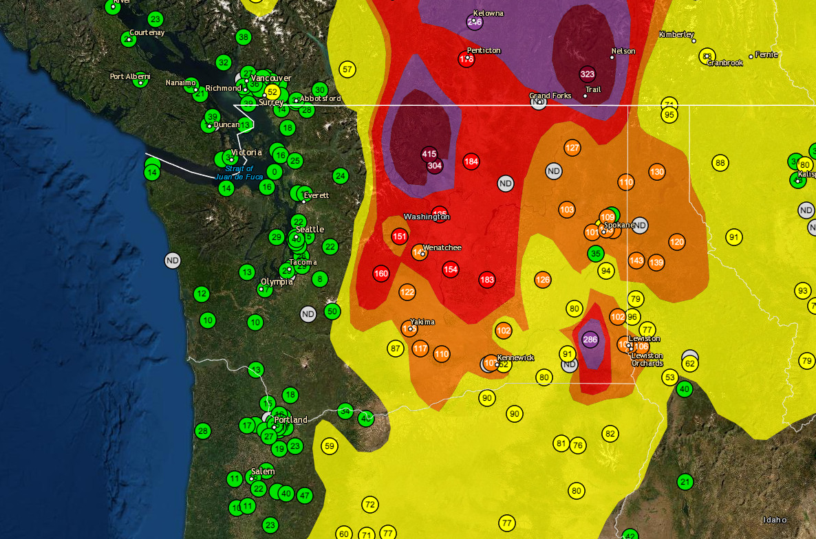
WA Air Quality; Aug. 1 2021Airnow.gov
A while back, I stumbled across the AirGradient project – a DIY air quality sensor built on the ESP8266 platform – and thought it would be interesting to build one to track the air quality where I live. AirGradient supports sensors for temperature/humidity, CO2, and – most importantly for air quality – PM2.5.
Of course, these are all low-end consumer-grade sensors. I wouldn’t trust them with my lung health, but I figured it’d provide another data point to add to the available local air quality measurements.
Sourcing Parts
The AirGradient site has a parts list that you need for the project. I ordered all of the components from AliExpress:
- ESP8266 “WeMos D1 Mini” ($1.98)
- SSD1306 0.66" 64x48 OLED Display ($2.47)
- SHT30 Temperature/Humidity Sensor ($3.02)
- PMS5003 PM2.5 Particular Sensor ($13.80)
- SenseAir S8 CO2 Sensor ($29.12)
The only other thing I had to source was the PCB that all the components are mounted on. AirGradient doesn’t sell the PCB themselves, but they’ve kindly released the PCB CAD files as open source, so I was able to order my own to be fabricated from JLCPCB. This was the first time I’d ever ordered my own PCBs, and I was surprised at how cheap the process was $5.50 total – including shipping – for 5 printed PCBs.1

Printed PCBs
All told, including shipping, the hardware cost was $62.88. Per the list above, about half of that cost came from the CO2 sensor. So, if you only care about sensing particular matter (PM2.5), you could make a setup that is significantly cheaper.
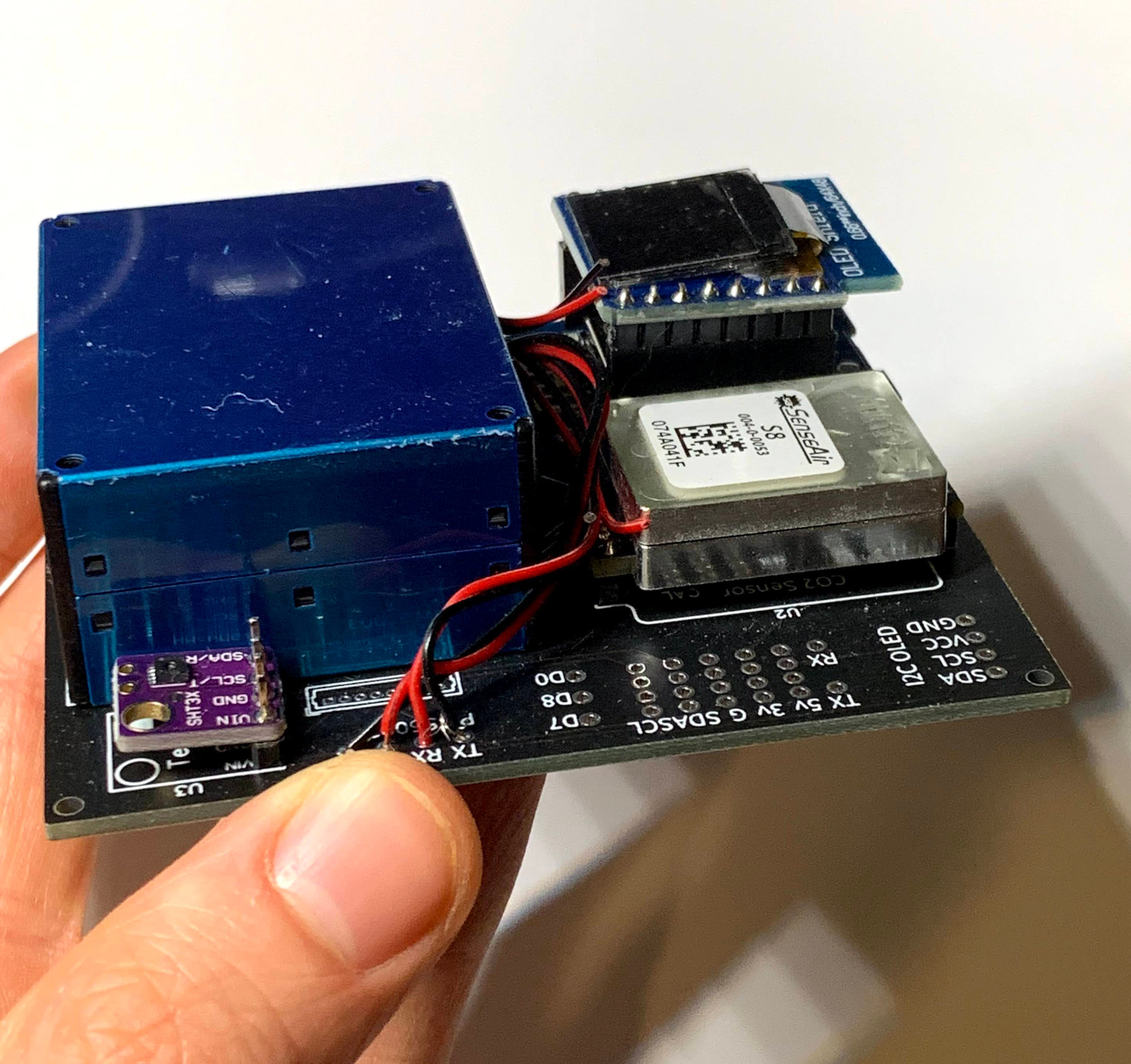
Assembly
There’s not much to say about assembly, actually. It was a relatively simple soldering project. The AirGradient PCB design is very well labeled, and has a bunch of additional test points to verify that everything is wired correctly.
The trickiest part is connecting the PM2.5 sensor to the board. That sensor outputs a ribbon cable which you have to split, strip the individual wires, and solder to sockets in the PCB. Not all that difficult, but definitely the most finicky part of the process.
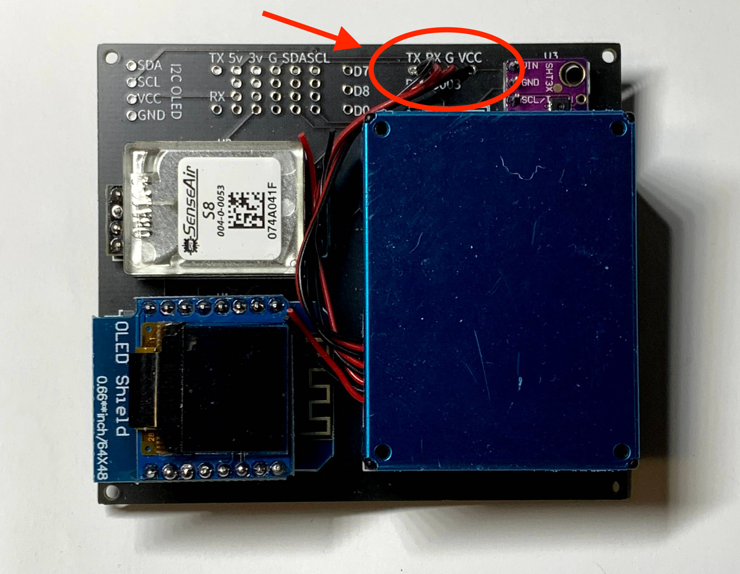
PM2.5 Ribbon Cable Soldering
Once done, the whole thing can be powered by a micro-USB cable plugged into the ESP8266.
Software
At first, I tried using the Arduino-based library that AirGradient publishes, following these instructions. It kinda worked, but I never got all of the sensors working correctly – the CO2 sensor in particular never reported data using their software.
Pretty quickly, I bailed on their library and looked for other options. I ended up settling on ESPHome. ESPHome is a YAML-configurable toolkit for setting up sensor monitoring (and event-driven automation). It has a quite large library of sensors, switches, displays, and other components that it supports.
You just create a YAML with the sensor definition, and ESPHome compiles a binary for your ESP8266 that monitors those sensors, and can publish the data to Home Assistant.
Fortunately, ESPHome supports all the sensors (and even the display) that AirGradient recommended, so I was able to get full sensor coverage.
# Example sensor configuration.
# Full config available at https://github.com/bcongdon/aqi-esphome
sensor:
    - platform: sht3xd
      temperature:
          id: temp
          name: "Temperature"
      humidity:
          id: humidity
          name: "Humidity"
      address: 0x44
      update_interval: 5s
    - platform: pmsx003
      type: PMS5003T
      uart_id: uart1
      pm_2_5:
          id: pm25
          name: "Particulate Matter <2.5µm Concentration"
    - platform: senseair
      uart_id: uart2
      co2:
          id: co2
          name: "SenseAir CO2 Value"
      update_interval: 60s
The full config I setup is on my Github. Right now, I have it cycling through temp/humidity and CO2/PM2.5 data. I haven’t quite figured out how to map PM2.5 to AQI yet, though this PDF describes how to do that conversion.
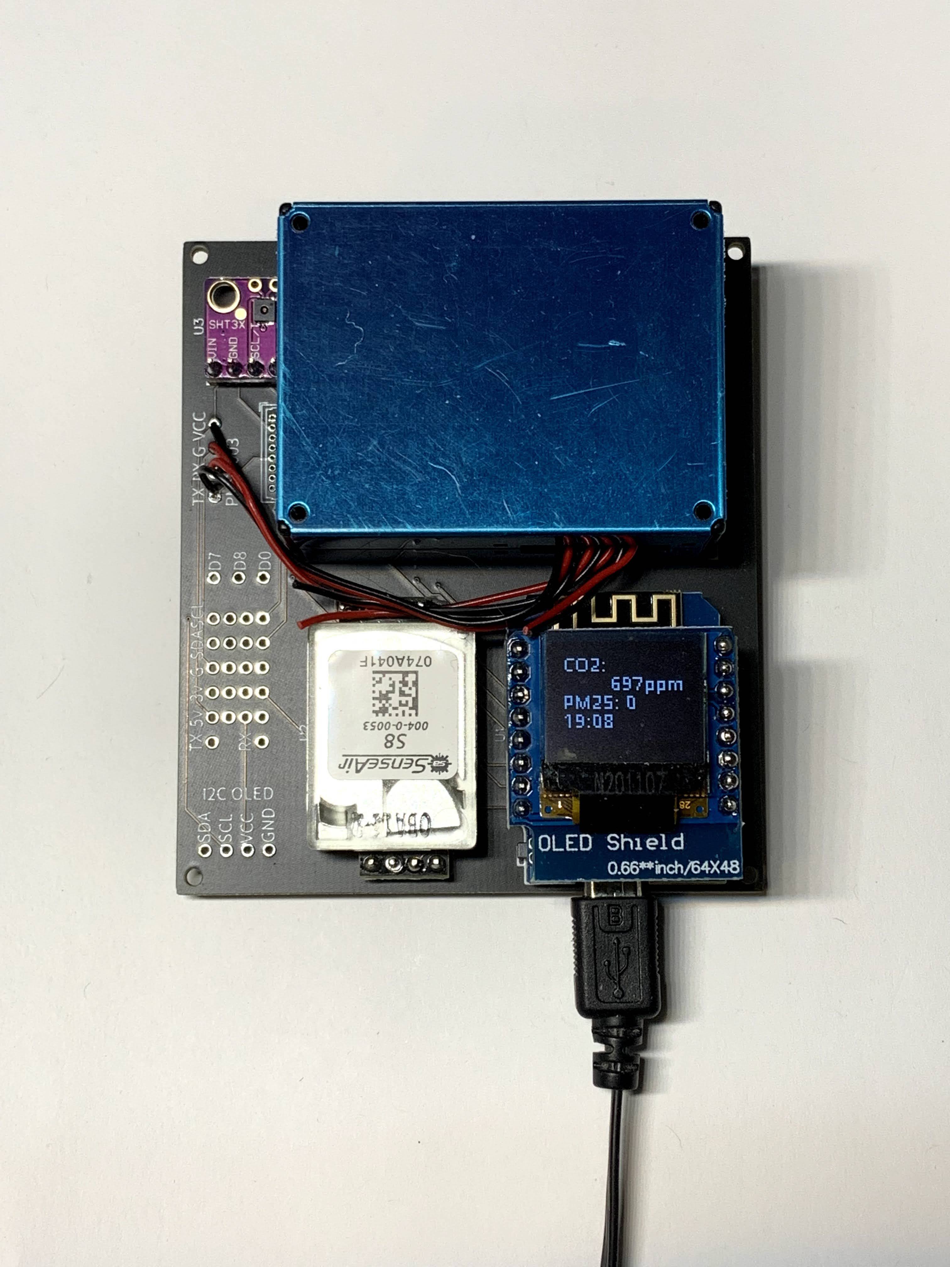
Powered on and displaying data
Enclosure
The AirGradient project also has CAD files for a 3D-printable enclosure for the device. Adding an enclosure is a nice “finishing” step, but in my experience everything works fine without one, and the finished board feels solid enough that I’m not concerned about it breaking. If/when I have access to a 3D printer again, I’ll probably make one of these:
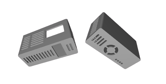
3D-Printable EnclosureAirGradient Project
Conclusion
So far, the data is (thankfully) pretty “boring”. The PM2.5 near my home is close to zero at baseline, and doesn’t change meaningfully in normal conditions. CO2 was a little more interesting – especially since there’s some correlation between indoor CO2 levels and various measures of wellbeing. The level I got from the CO2 sensor was never high enough to be alarming, but I could definitely see a difference between well- and poorly-ventilated rooms.
Hopefully the data remains “boring” (🤞), but I’ll try to post an update once the wildfire season kicks off to track how this worked.
Update, November 2021: Achim from AirGradient reached out and let me know that AirGradient is selling DIY kits (including the PCB). I haven’t tried out the kit, but it seems like a promising option.
-
I still can’t quite wrap my head around how inexpensive it was to manufacture these custom PCBs. They aren’t particularly complicated, but I would have assumed that the cost to setup the tooling for a new PCB design would be in the $100s. ↩︎