Earlier this year, I built a DIY pen plotter (mostly) from scratch. I’d been meaning to post a build log, because this was one of the more enjoyable hardware projects I’ve worked on recently. However, it’s taken a while to write-up this project because, well, there was a lot of stuff going on.
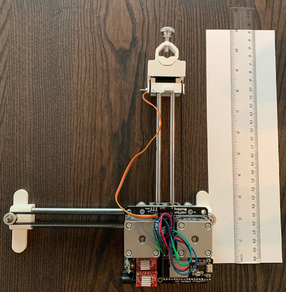
Completed Plotter with Ruler for Scale
Why Build a Plotter?
So, why is it worth building a pen plotter? The short answer is, “they’re cool”. The longer answer is that, despite commercial printers (ink jet, laser, etc.) working better for general purpose printing, the quality of a pen-plotted image is noticeably different than something that’s been traditionally printed. Plotted images can have a more natural, organic feeling to them, because they’re produced by raising and lowering a pen manually, like a human does.1
I’ve also had a persistent curiosity with generative art. Much of the community built around generative art (colloquially, #plottertwitter) uses pen plotters to turn “bits into atoms”. While most folks opt to buy a commercial plotter like the Axidraw or restore vintage plotters from the 1980’s, there’s a growing community of people building their own plotters.
Assembling the Components
The first step in the project was collecting the bill of materials (BOM). There’s a well-researched BOM on the project Github. Other than the midTbot PCB, which is for sale on Tindie, I had to order:
- Linear shafts and Linear Bearings (Amazon)
- Pulleys and Idler Pulleys (Amazon)
- Rubber Timing Belt (Amazon)
- 2 Stepper Motors (Amazon)
- Stepper Motor Controllers (Amazon)
- 12V 3A Power Supply (Already had one)
- Basic Hobby Servo Motor (Already had one from previous Arduino projects)
- Assorted M3/M5 Head Screws (Home Depot, Ali Express)
I was pleasantly surprised how available most of the parts were online – everything except for the screws/nuts were available on Amazon.
Once I received my midTbot PCB, there was some soldering and assembly to do. I followed these instructions to attach the homing switches, power supply, and header pins to the board.
Printing the Chassis
The chassis of the midTbot is entirely 3D printed. There are ~7 things that you need to print (source files on Github), and they’re all fairly simple shapes, so the prints were easy to do.
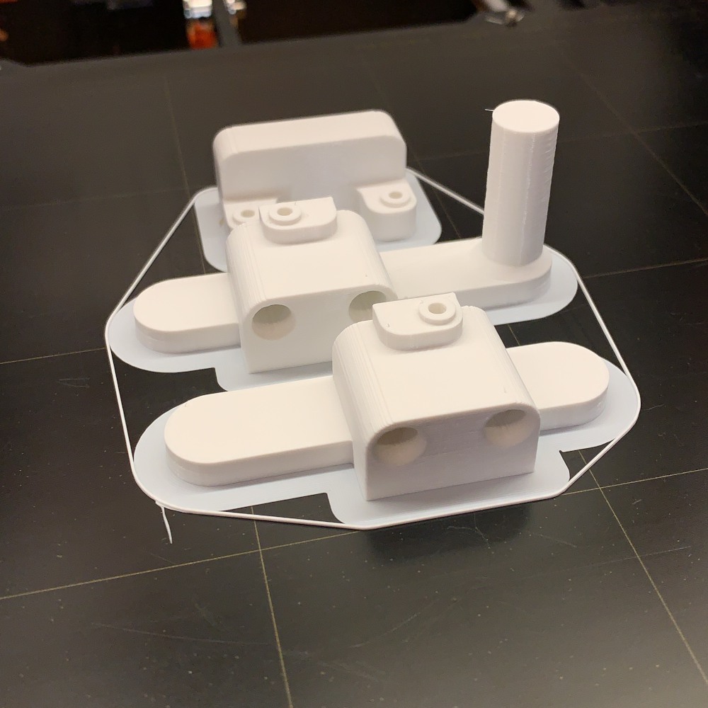
Completed prints of the ‘feet’ and tailblock pieces
The hardest thing to print (and the most finicky part of the project in general) was the pen mount. This piece has some overhangs on it, so it was important to configure the printer to add support material.
Assembly
With the PCB assembled, mechanical parts purchased, and chassis pieces printed, it was time to do the final assembly. Again, I followed the assembly instructions on the project Github.
The assembly process was straightforward: the PCB gets screwed into one of the printed pieces, the pulleys and linear rods get screwed in to the “feet” and carriage block pieces, and the stepper motors are secured to the chassis with the PCB “sandwiched” in between the chassis and the motors.
One difficult step was attaching the stepper motors to the PCB. Per the project instructions, you’re supposed to solder the stepper motor wires into plastic pin sockets, so you can easily detach the motors from the PCB. But, after I tried and failed several times to solder the stepper motors into the female socket block, I simply soldered the female sockets to the board directly and soldered the stepper motor wires onto solid-core jumper wires. The end result wasn’t as clean as what’s shown in the project instructions, but still allowed me to hot-swap the motors if needed.2
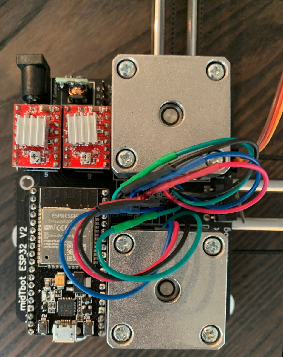
Controller (Bottom Left), Motor Drivers (Top Left), Stepper Motors (Right)
Once the main “chunk” of the plotter was assembled (pictured above), the only things left to do were to thread the timing belt around the pulleys, and attach both ends of the belt to the pen head with a small amount of tension.
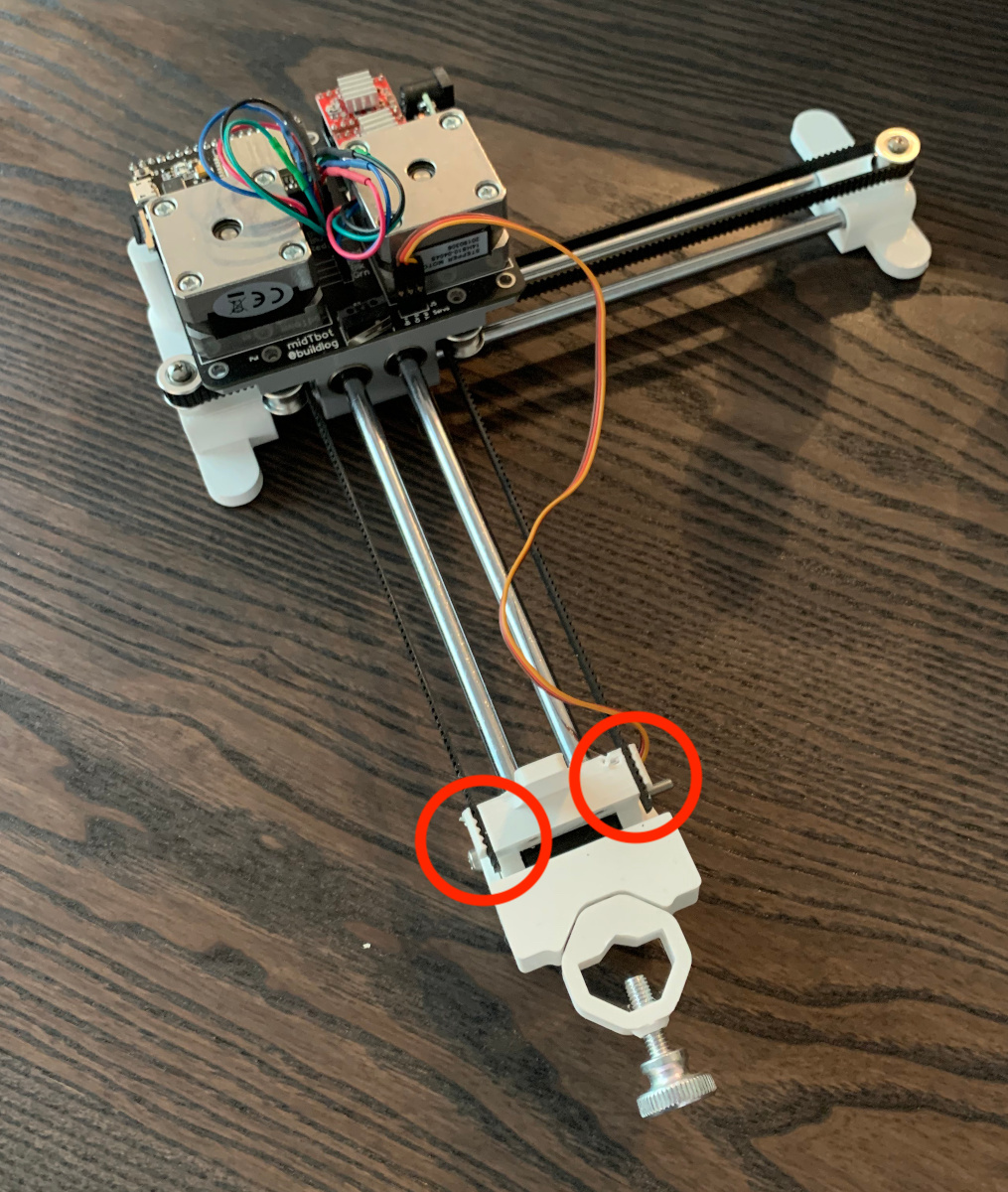
Belt Attach Points (circled)
The last step in assembly (and, unfortunately the most fiddly part of the whole process) was attaching the pen holder to the “head” block. The long screw that makes the joint between the pen holder and “head” block needs to be tuned meticulously: If the screw is too tight, then the pen can get stuck in the “up” position – not returning to the “down” position when the servo retracts. On the other hand, if the screw is too loose, then this translates to “slop” in the pen’s position, which results in wiggly drawings that are unusable.

Pen Lift Servo Mechanism, Joint Screw/Nut (Arrow)
At this point, the bot was assembled! I powered it on and installed a specific version of the Grbl_Esp32 firmware designed for the midTbot per the project instructions. Grbl_Esp32 is a really nifty piece of software: it allows you to upload an run Gcode (basically, machine readable instructions for how to move the pen) on the plotter’s Esp32 controller. Since the Esp32 has built-in wifi (and bluetooth), its able to serve a basic web UI:
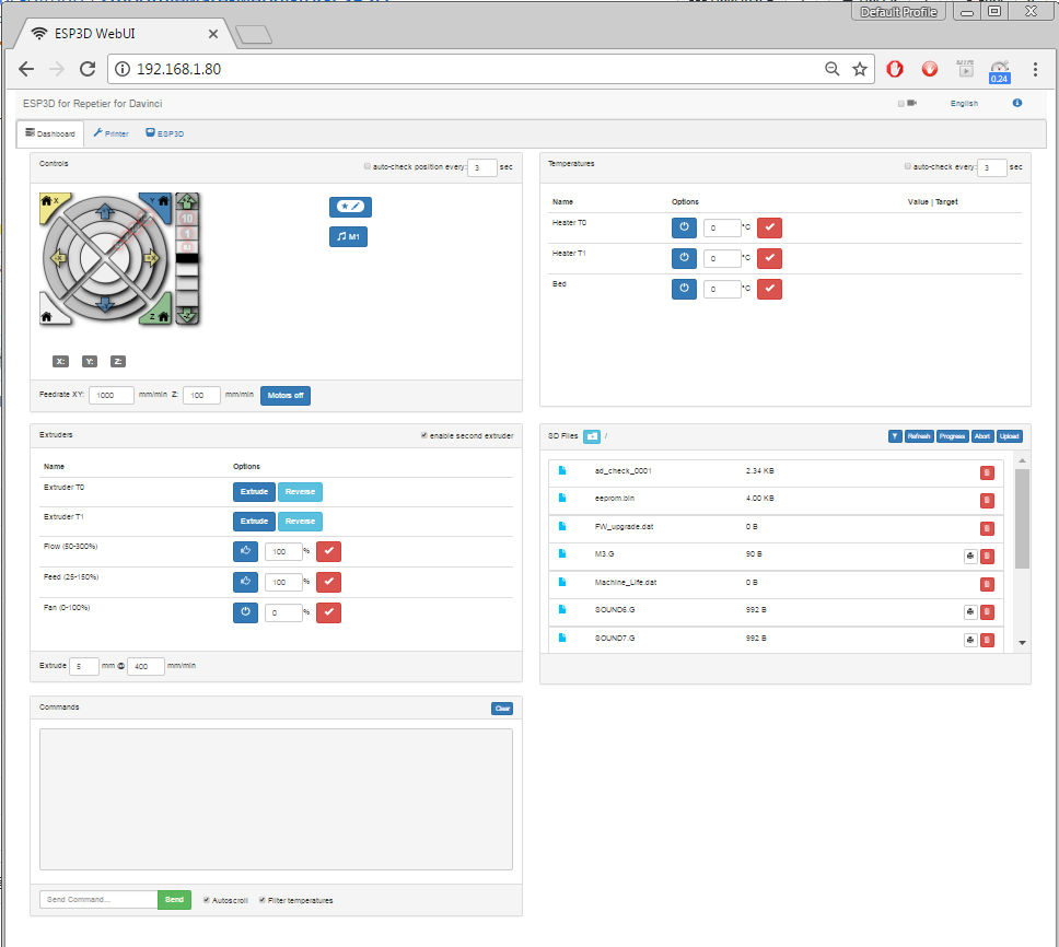
Grbl_Esp32 Web UISource: Github
The Web UI is sufficient for most tasks: homing, minor positioning adjustments, starting/pausing/resuming prints. There are only a few tasks – like calibration – that require you to drop down to the Grbl “command line”.
It took me a while to get my midTbot calibrated. The project documentation was a bit light on the specifics, so there was a lot of trial-and-error and troubleshooting.
Plotting, Software
Now that I had a functioning plotter bot, the next thing to do was try it out. Of course, to do so you need to actually produce Gcode that the bot can use. There are tons of tools to do this – and a full discussion of Gcode/plotter software is worth a whole other post. Suffice it to say, there are a variety of resources on the Drawing Bots community page that serve as a good starting point.
I spent most of my time working with Inkscape’s Gcodetools plugin. Axidraw (which makes a commercial pen plotter) also has some useful Inkscape plugins, although some of the functionality won’t work with the midTbot. Gcodetools nominally allows you to translate SVGs to Gcode, however this is a tedious process. Not just any SVG will work well with it; the SVG basically already needs to be a line drawing for Gcodetools to have any hope of working correctly. It has basic support for infilled regions too, but again you have to be careful with it – any slight hiccup, and it produces unusable Gcode.
To be honest, the software aspect of pen plotting is the most frustrating part of the workflow. I haven’t yet found a great toolchain for the “art” -> Gcode pipeline, so there’s a lot of finicky steps. (It doesn’t help that Inkscape is a second-class X11 app on macOS…)
Additional Hardware Modifications
After I ordered a midTbot PCB, the creator added me to a Slack group. Some of the other folks who’d built midTbots contributed back modifications they’d made to their builds. I took a couple of these and added them to my bot too:
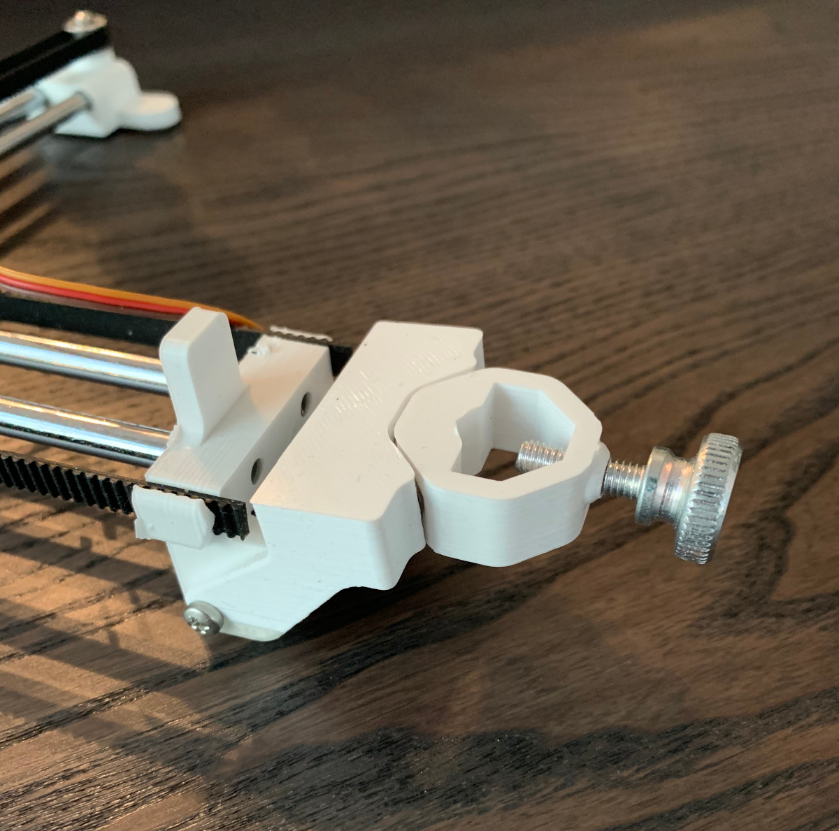
Magnetic Pen Mount with Thumb Screw
First, I ordered heftier thumb screws for the pen attachment (as pictured); the screws in the original BOM are tricky to manipulate by hand. Second, I printed a magnetic detachable pen holder (as pictured) which makes it easier to add/remove pens without disturbing the rest of the setup. If you want to do multicolor prints, this modification is a must. Finally, I printed wider supports for the bots frame. Supposedly, this allows you to increase the available print size of the bot (if you also order longer linear rods). I didn’t get around to actually increasing my bot’s print size, but the wider supports made the bot more stable, and easier to attach to a work table.
Results
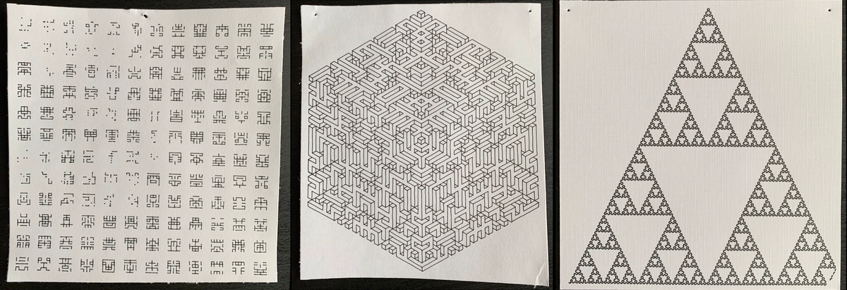
After an afternoon of calibrating the bot and installing the mods I discussed above, I got some prints that I’m pretty happy with.
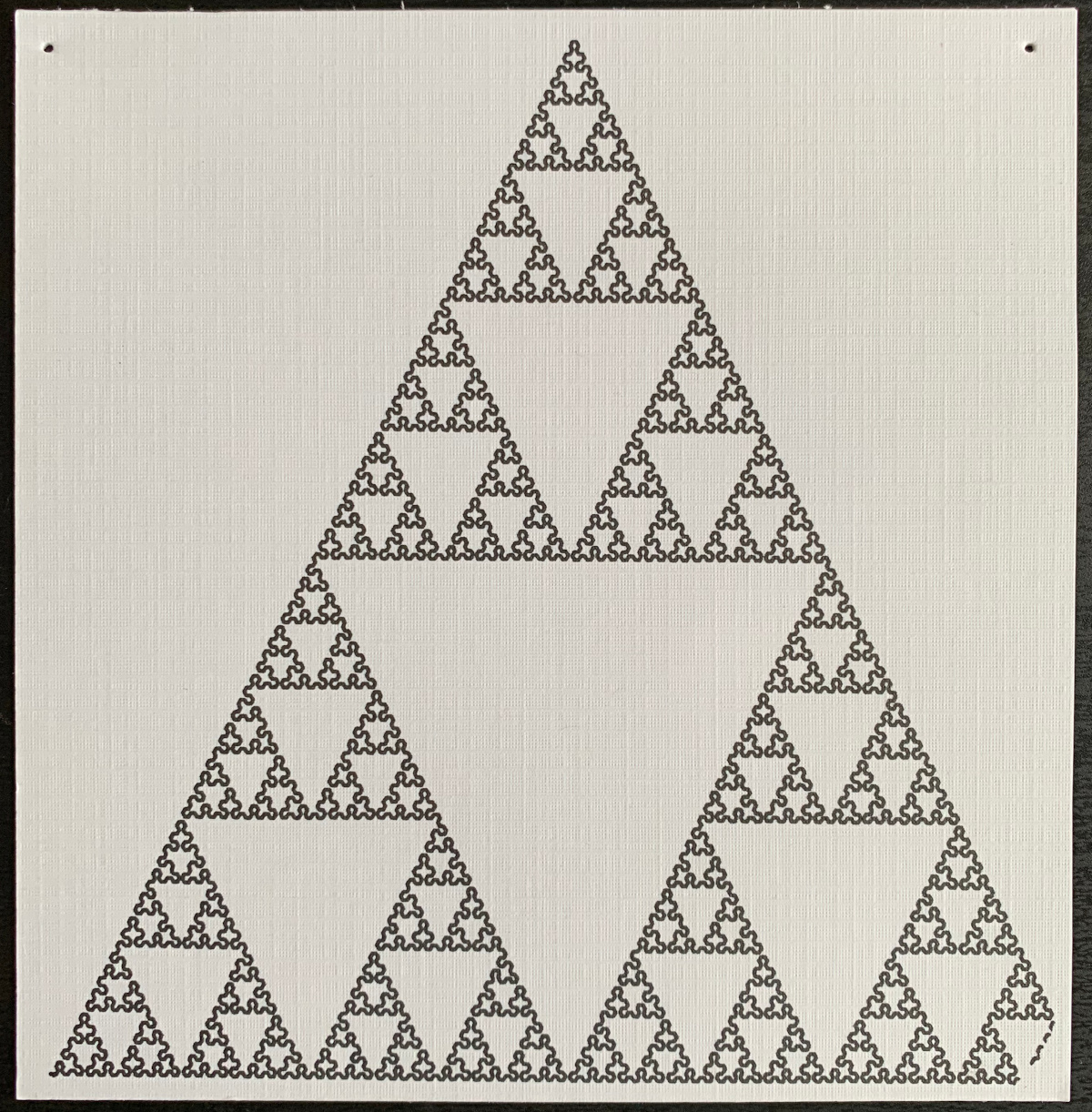
Sierpinski’s triangle (above) is a single line, but has a lot of intricate detail. This is a good exercise of the precision of the stepper motors, which as you can see is quite good. The precision also requires the pen mount to be calibrated correctly, so that there isn’t any “slop” between the pen and the body of the plotter.
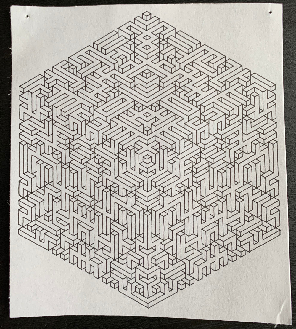
Isometric CubeSource: Github
This was a slightly harder pattern for the bot to draw. The lines are all straight, but there are a fair number of pen raises. Generally, the more pen up/down cycles a print has, the greater the likelihood of failure.
I’ve also noticed that where the pattern is in the print area of the bot makes a difference. The closer the pen head is to the main bot chassis, the more the pen is pulled away from the paper due to the counterweight of the “tail” section. As such, I tried to position the prints as close to the middle of the print area as possible. Below is what happens when the pen holder misbehaves:
Somewhat failed ‘Space Invaders’ Print (Note the discontinous/missing lines)Source: vpype Example Code
The plot isn’t a complete failure, but many of the lines don’t get drawn or only get partially drawn. This is often caused by the pen mount screw being too tight, causing the pen to get stuck in the “up” position periodically.
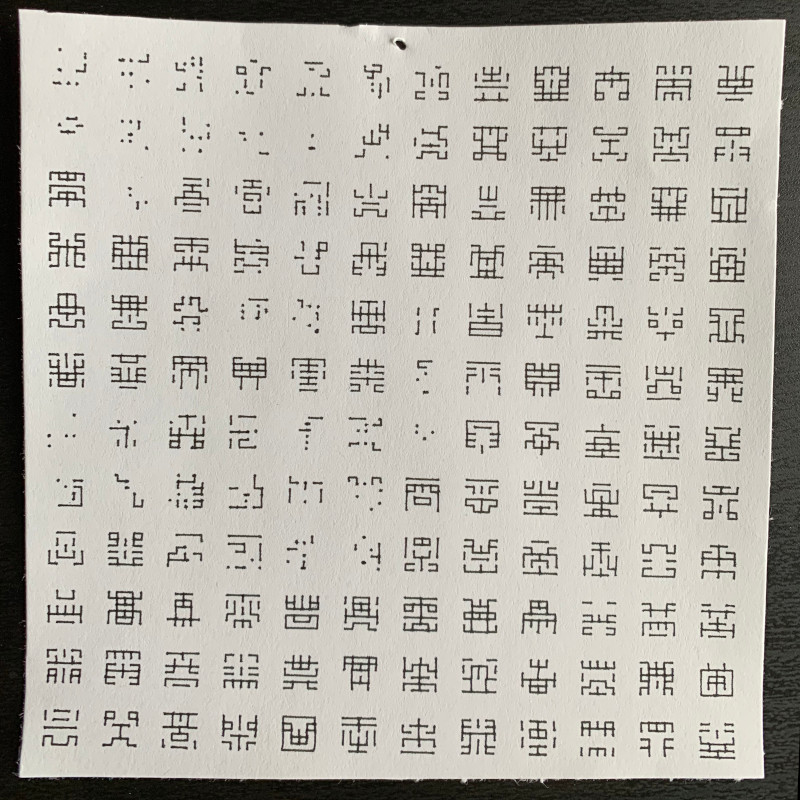
After I’d spent some time acclimating myself to the bot, its firmware, and creating Gcode, I was able to get it to be pretty consistent – even when a print had a large number of pen cycles. I’m at the point where I can have it print text (albeit quite slowly) without any noticeable glitching or broken lines:
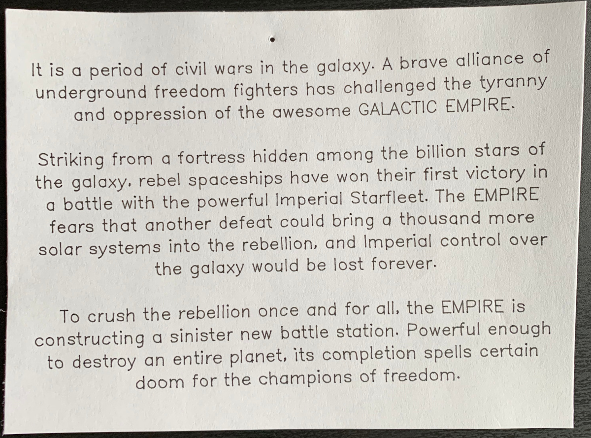
On a lucky day, text renders quite well!
Conclusion
This was a fun project! I flexed my soldering skills and learned how to use a 3D printer. I’m very happy with how the hardware portion of this project turned out. There are still a few ergonomic things I’d like to adjust to make the plotter more consistent – perhaps affixing it semi-permanently to a drawing mat to make it easier to align paper under the printer.
There’s still quite a bit of work on the software front to make the printing process easier. Ideally, this is something that you’d want to be able to iterate quickly on – trying different pen sizes, making slight adjustments to the printed pattern, et cetera. Right now, the process is too fiddly for that to be a fun experience.
I’d recommend building one of these if you’re interested in pen plotters and/or generative art. The build process was fun, and the completed bot is quite functional!
Additional Resources
- midTbot on Tindie (PCB kits for purchase)
- midTbot on Github
- midTbot on Thingiverse
-
This is why most automatic signature robots are essentially pen plotters. ↩︎
-
It turns out that having the ability to connect/disconnect the stepper motors quickly is important, as in the calibration process you may need to reverse the polarity of one or both of the motors. ↩︎